Quite recently my wife lost her vaccination passport somewhere in our flat and we could not find it. A year ago, I searched 3 hours for my laptop, only to find that my robot vacuum had hidden it under the bed while it was cleaning. Searching for these things stresses me out, even if I know they must be somewhere in the flat.
Since lost items are a common issue, there must be a technical solution. This blog posts describes how a built an UHF RFID system that utilizes passive tags to find items I lost in my flat.
Available technology
In 2021, Apple released AirTag. Its a small keyfob-style device that uses Bluetooth LE and Apple’s FindMy network to locate lost items across the globe. It also includes a UWB antenna that precisely homes in the device location on a centimeter-scale. However, these capabilities come at a cost. AirTags require a coin-cell battery that needs to be replaced yearly, are quite bulky, and relatively expensive. In packs of 4, each tags costs upwards 30€. This makes AirTags good for few high value items, like keys and wallets, but having an AirTag on every vaccination passport and electric toothbrush would require thousands of Euros in investment and daily battery swaps.
Bluetooth-based trackers from other companies suffer the same issues: price, battery, and size. For the technology to be practical it must not require a battery, be thin, and comparatively cheap. Target cost is less than one Euro per item. One technology on the market is promising: RFID.
UHF RFID
RFID, or radio-frequency identification, describes a technology to identify and track tags by a reading antenna. RFID tags are passive and consume their sending energy from the electromagnetic field generated by the antenna. (There are active tags with a battery but those are only used in few commercial applications). The RFID tags themselves are usually mass-produced printed circuits what makes them very cheap and thin. RFID tags are used everywhere: In production facilities, security systems, and clothing stores. Decathlon sews in an RFID tag to every of their clothing pieces for quicker checkout and shoplift detection. Most smartphones have an RFID reader embedded, since NFC is an extension of the RFID HF standard. Wireless credit cards also use NFC technology.
The biggest issue with RFID application to find items is the detection range. Since the tags are passive they must harvest all their sending energy from the antenna’s electro-magnetic field. The field strength drops quickly with increased distance. RFID defines different frequencies for tag identification:
- LF (125 kHz) for short-range (few centimeters)
- HF (13.56 Mhz) for mid-range (around 50cm)
- UHF (865 or 920 Mhz) for long-range (up to 10m)
Given by these variables only UHF RFID may be used to find lost items in a considerable range. While LF and HF RFID are common in private appliances and readers are easily available for cheap, UHF RFID is primarily used by industrial customers. This makes sourcing technology and tags quite a bit harder and expensive.
Please note that the ISM rules for UHF RFID only allow an indoor usage. Outdoor usage may jam other users like LoRaWAN because of the RFID readers broad spectrum and high power output.
Sourcing the hardware
For UHF RFID, two major bands are used: 865–868 MHz in Europe and 902–928 MHz for pretty much the rest of the world. Therefore, it would be preferable to purchase EU RFID equipment to not violate any frequency guidelines. Unfortunately, all RFID readers I could find in European shops were industry-grade and stupidly expensive. They also require software licenses for industry good tracking software suites that I do not posses. The only option to purchase an UHF RFID reader was China in the form of Aliexpress.
On Aliexpress there is a variety of relatively cheap UHF RFID hardware. Dedicated reader modules and antennas, as well as integrated readers with both components are on offer. The sellers advertise these systems for parking control and participant tracking in sports events. Prices range from 50€ for a small desktop-grade reader up to several hundred Euro for reader with multiple antenna inputs. I decided to purchase an integrated reader for price and comparability reasons. Feature-wise the reader should offer RSSI detection (basically displaying how strong the tag signal is) and should be configurable to EU frequency bands.
What I ended up with was the boom barrier gate car parking access system 6m UHF RFID card reader long range Antenna Reader 1-6M Integrative from Zocorfid. The model is R16-7DB and it is offered by various sellers. It costs around 80€ with shipping to Germany and has USB and RS232 outputs. The reader can be configured using an SDK provided by the vendor and comes with two sample tags.
For this build I also used some other components I had lying around from previous projects:
- Raspberry Pi Zero WH
- MicroUSB OTG adapter
- 3.5" Waveshare compatible RPI display from Berrybase
- Generic 1.5A USB powerbank
- Velcro zip-ties
- Some screws for the Raspberry Pi
Configuring the reader
The reader arrived about two weeks after the purchase. Hooked up to a 12V power source or USB it beeps loudly when it identifies a tag and flashes a green LED. The read range was very promising and averaged around 5m without obstacles. After testing the device I wrote to the email address on the backside to receive the SDK. By default, the reader emulates a serial interface on the USB port and spits out the IDs of all detected tags. I needed to change two things: The reader should also send the signal strength (RSSI) of the identified tag and needs to be configured to the EU frequency band. The seller sent me a WeShare link for the software.
├── UHF reader Demo sdk
│ ├── DEMO(C#)
│ │ ├── DLLProject.dll
│ │ └── RFID_EPC_Project.exe
│ ├── Document of Interface Functions.docx
│ ├── Document of Interface Functions.pdf
│ ├── R16-7DB specification(1).docx
│ ├── RFID_EPC_Project(C#)
│ │ └── RFID_EPC_Project(C#)
│ │ ├── DLLProject.cs
│ │ ├── DLLProject.dll
│ │ ├── Form1.cs
│ │ ├── Form1.Designer.cs
│ │ ├── Form1.resx
│ │ ├── Program.cs
│ │ ├── Properties
│ │ │ ├── AssemblyInfo.cs
│ │ │ ├── Resources.Designer.cs
│ │ │ ├── Resources.resx
│ │ │ ├── Settings.Designer.cs
│ │ │ └── Settings.settings
│ │ └── RFID_EPC_Project.csproj
│ └── RFID_EPC_Project_EXE(2019082906)
│ ├── DLLProject.dll
│ ├── IpInputBoxLibrary.dll
│ └── RFID_EPC_Project.exe
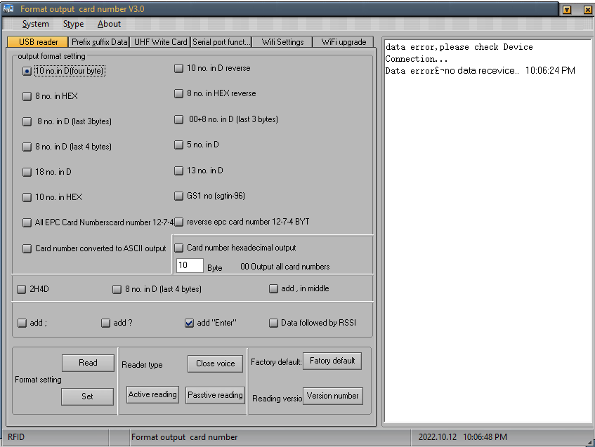
└── UHF RFID software V30
├── UHF RFID software V3.0.exe
├── UHF setting software manualv2.7.docx
└── usb.dll
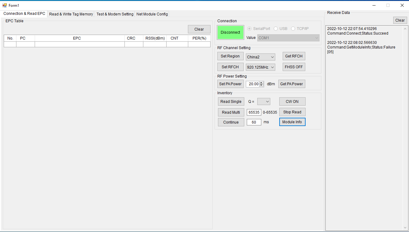
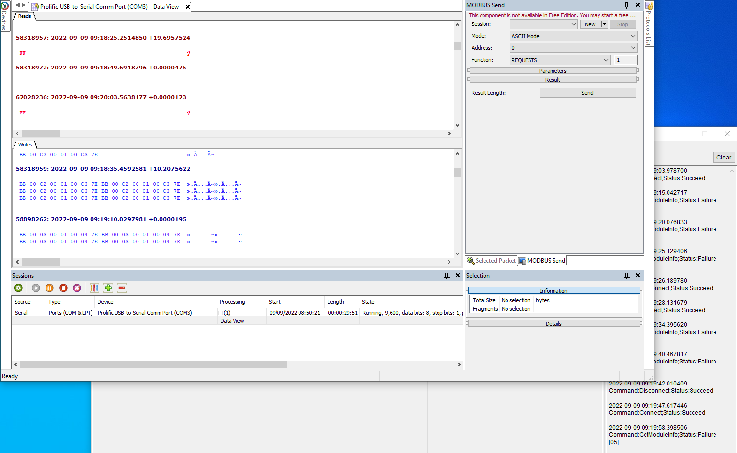
The software is a hot mess. Its basically an SDK and multiple stages of a reference implementation. There seem to be two major software components: “UHF RFID software V3.0.exe” which has a nice icon and “RFID_EPC_Project.exe” which looks like a more generic SDK GUI. I am not going to elaborate on the ultra-weird quirks of the software, like a theme selection (“Stype”), the option “Exist” in the file menu, or the very vague English translations. My biggest issue with the software was: It did not work. No matter how I connected the reader (USB, RS232) or what I did, every command input just showed an error message.
Over several days I played around with different serial adapters, and Windows compatibility options. Sometimes a command seemed to have the reader and it even made a beeping sound, but subsequent commands failed. Desperate, I disassembled the reader to find a clue how to progress.
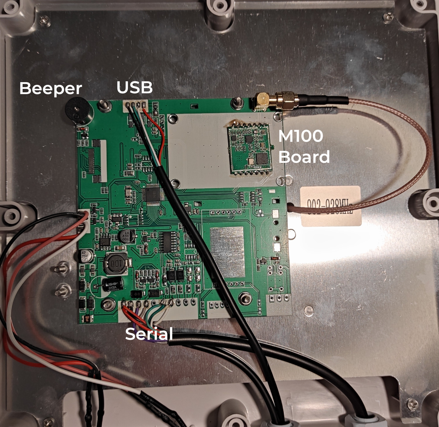
The reader itself consists of three components: A main board, a daughter RFID board, and the antenna. The antenna is a 920 MHz model which should lead to worse performance when configured to an EU frequency band. The RFID daughter board uses a MagicRF M100 chipset. This chipset is actually well documented and the documentation matches the options offered by the SDK. Therefore, the SDK only is an an implementation of the MagigRF M100 command set. Sniffing the traffic of the SDK on serial showed that the sent commands are the same as documented for the chipset.
This know-how did not bring me closer to a solution. I tinkered with the timings of when the power and serial are connected and also connected power and USB in parallel. Some day, things just worked out and I was able to set the desired settings: EU frequency band and RSSI included in the USB serial output. I was not able to get it working again anytime after, but I had achieved my target. In the short window of opportunity I forgot to turn the beeper of. I physically destroyed it on the board, as its super annoying.
For anyone trying to replicate this, some potentially helpful observations:
- Even though the USB interface emulates a serial port, it is not the same as the RS232 interface. Configuration only worked via RS232 for me. They are also soldered to different portions of the motherboard.
- The SDK only sends MagicRF M100 commands, and debugging is easier by sending them directly or via a script
- 12V was connected during my successful programming
- It would be nice to use the MagicRF “select” features when searching for tags if the connection worked reliably
- The USB serial sometimes just spits out random characters - I filter these out in software
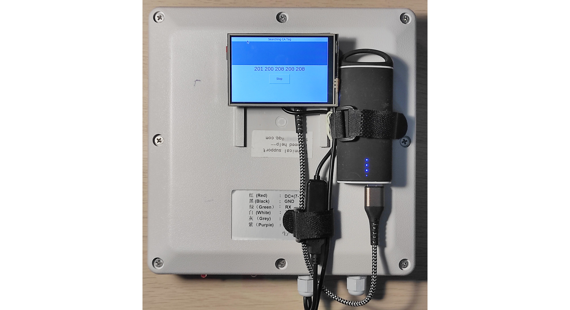
Assembly
To make use of the reader I needed to provide a user interface that allows to select tags to search and show the signal strength. I thought about building a smartphone app but ultimately decided to go for a fully integrated option to reduce future maintenance. The user interface and search logic is implemented on a Raspberry Pi Zero WH. It features an SPI touchscreen display for the user interface. The reader is hooked up via the Raspberry’s USB OTG port. Since the reader is powered via USB, a single powerbank powers the entire system.
On the Raspberry I installed Raspbian with the lxde user interface. I then installed the waveshare display drivers and set the boot target to graphical in the raspi-config tool. For some reason, the waveshare driver selected the wrong framebuffer interface: I had to change “fb0” in /usr/share/X11/xorg.conf.d/99-fbturbo.conf to “fb1”.
After lxde worked I removed the lxde desktop process from the startup procedure created a systemd service file to start my custom RFID search application. The service must be given some environment variables so it can connect to the X.org server:
[Service]
Environment="DISPLAY=:0"
Environment=XAUTORITY=/home/${user_name}/.Xauthority
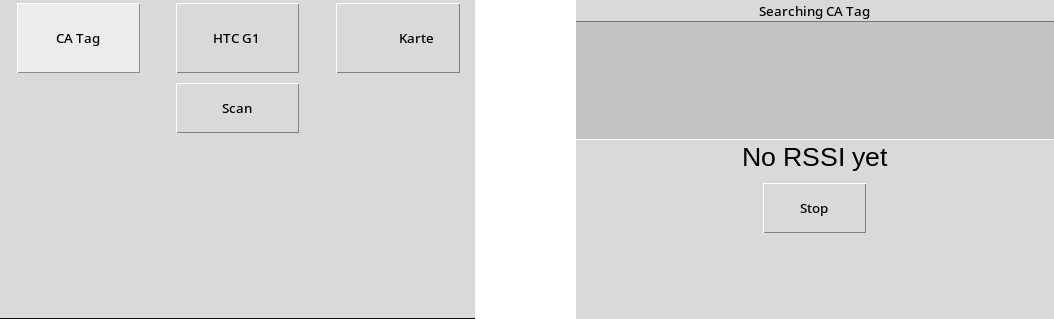
With the systemd service in place I wrote a small Tk-based Python application that reads a CSV file for tags and generated a button for each findable tag. It also features a pretty basic gauge to home in on the tag based on the RSSI.
To remove the scripts header bar and eliminate scrollbars, I set some options in the lxde configuration for the generated windows:
<applications>
    <application name="tk">
        <fullscreen>true</fullescreen>
        <decor>no</decor>
    </application>

    <application class="Toplevel">
            <fullscreen>true</fullescreen>
            <decor>no</decor>
    </application>
...
</applications>
The CSV file is stored on the SD-card of the Raspberry. A more advanced option would be to store the file on some remote server or even create a companion app that allows to edit the tags on a smartphone. Since I do not change the tags too often the current implementation is fine for me: The app displays the token ID and I manually add it to the CSV together with the name of the item.
Measured performance
To give an indication of the possible detection range, I made the following measurements with different obstacles between the tag and reader, as well as different tag orientations. During the test the tag was mounted on different surfaces. The obstacles were placed directly in front of the tag.
Tested orientations:
- 0°: The surface area of the tag and the antenna are parallel to maximize electric coupling (| |)
- 45°: The surface area of the tag and the antenna are twisted by 45° in one dimension (| /)
- 90°: The surface area of the tag and the antenna are orthogonal to each other (| -)
Tested obstacles:
- None: Only air between tag and reader
- Magazine: 162-page paper magazine
- Wood: 18mm thick pine board
- Clothes: 5cm high stack of layered clothing
- Malm: Tag fixed to the inside of an Ikea Malm drawer
- Drywall: Drywall with steel frame
- Alu: Thin sheet of Aluminum
Tested surfaces:
- None: Fixed to the obstacle, only air behind the tag
- Wood: Tag backed by 18mm thick pine board
- Malm: Tag inside Ikea Malm drawer
- Concrete: Tag backed by a steel-reinforced concrete wall
I did not test all permutations for time constraints. Since high-frequency RF is magic by definition, the resuls may be very different in another environment than my home.
C&A hang-tag
The best tag I own is a hang-tag from a T-Shirt sold by the fashion retailer C&A. It is a quadratic tag that performs much better than the tags that came with the reader itself. Maxed out measurements (">Xm") indicate that I had no larger space in my flat to test.
| Obstacle | Orientation | Surface | Distance |
|---|---|---|---|
| None | 0° | None | >6m |
| None | 45° | None | 3m |
| None | 90° | None | 2.5m |
| Magazine | 0° | None | 3m |
| Magazine | 90° | None | 2.5m |
| Wood | 0° | None | >6m |
| Clothes | 0° | None | >6m |
| Malm | 0° | Malm | >4m |
| Malm | 90° | Malm | 3m |
| None | 0° | Wood | >6m |
| None | 90° | Wood | 5m |
| Magazine | 0° | Wood | 5.5m |
| None | 0° | Concrete | >2.5m |
| Wood | 0° | Concrete | 1.5m |
| Drywall | 0° | None | 2.5m |
| Aluminum | 0° | None | 2m |
The tag did not penetrate from the inside of a fridge made of stainless steel.
Original tag
The original tag that comes with the reader is a rectangular “M4/H3” tag with a relatively large surface area but thick layers. Compared to the C&A tag the performance is much worse. The unobstructed reading distance is around 1.5 meters.
Other tags
I have ordered a bunch of different tags on Aliexpress to test which of those come close to the C&A tag. I will add information on their performance here after I received them. My goal is to find a source of cheap and high performance tags in smaller quantities than the 5000 tag standard orders required by most B2B shops. Tags with the “Alien 4” chipset seem promising to me right now.
Tag performance factors
Metal close to or in between the tag and reader greatly affects the reading distance. Non-conductive materials close to the tag are less of an issue. For professional users very expensive “metal ready” tags are sold that have an isolating layer between the tag and surface. Not all tags are created equal. Generally, a larger surface area of the tag as well as a longer (and thinner) coil contribute to reading performance. Another factor are the build-in chips on the tag itself.
Real life performance
To test real life usefulness of the device I built I asked somebody to hide the C&A tag somewhere in my 65m² flat. In two tests I was able to narrow down the search window to a 1m x 1m area in less than a minute. Finding the tag then involved a combination of the reader and manual search. It turns out that it is easier to search for things that were actually lost. While the tag could be hidden anywhere, in real-world scenarios nobody is going to loose their vaccination card in the inside of a lamp shade. This makes the last step of manual search a lot easier for real objects.
When your kids wear decathlon clothing, the reader definitely is the ultimate hide and seek device.
Future improvements
Some improvements could be made to the hardware of the system as well as software components.
Hardware
A more powerful reader that maxes out the 2W ERP limit in Germany would improve reading distance. My model (R16-7DB) only has 1W of power output. More power means more detection range. The same counts for higher-gain antennas. From the same product line, possible models would be the R16-10DB or R16-12DB.
Generally I would recommend to use another model line of reader to work around the software issues. There are some other readers with the MagicRF M100 chipset that might be worth a look. During my research I also stumbled across systems made by “Shenzhen Fonkan Technology Co.” that promise to use a proprietary chipset and more mature software for a similar price. Other vendors to look at are chipsets by “Alien Technology” and “Impinj”. If you have any experience with these readers, please drop me a note.
The boot time of the Raspberry is rather long and could be shortened by cleaning up the operating system, using a newer Raspberry Pi model or changing the architecture to something like an ESP32.
Additional angled RFID antennas on the side of the device would make homing in on searched items easier. These antennas could be passive as the tag is powered by the main antenna. The difference of signal strength from these smaller antennas would allow to indicate the direction of the item for the user, similar to the AirTags UWB feature.
Some sort of 3D-printed back cover would make the device look nicer.
Software
Many RFID tags offer some sort of programmable data fields apart from the baked-in ID. One could store the name of the tagged item in the tag itself. This would allow to search for items by their name without known the exact ID. A big change would be some sort of smartphone app to learn tags on the go and provide a smoother UI.
Conclusion
I rather like this project. If I manage to find a reliable source of working RFID tags it is pretty useful and relieves me in one of my least favorite tasks. The system performs very well in “it should be here, is it worth to dig through this drawer”. This is all I could ask for.
If you have any questions or comments, feel free to write me on Twitter or mail to contact [ at ] ciko dot io.