In one of my spare parts boxes, I still had two Minolta A-mount SLR lenses lying around. The lenses (a 28-80mm f3.5-5.6 AF ZOOM and a 75-300mm f4.5-5.6 AF ZOOM) are about 25 years old but still work with modern Sony cameras. Since I only own a Nikon, I thought of some other use for these lenses. I found a Raspberry Camera Module v1 with a 5 Megapixel OmniVision OV5647 sensor in the same box. Wouldn’t it be funny to combine these SLR lenses with the camera module? The OV5647 sensor is much smaller than the original APS-C sensors, which should result in a massive crop factor of 9.30 and a super-zoomed image. When the 300mm f5.6 zoom is mounted, it should be equivalent to a 2790mm f/52 lens! To me, that sounded interesting enough to give it a shot. The Nikon P1000 created a buzz on the internet with its 3000mm equivalent lens, and the modded camera should be in the same range. Of course, the 25-year-old 300mm Minolta lens will not have the same optical quality, but how good can a setup with a total worth of around 30€ (Raspberry Pi not included) compare against a >1000€ professional camera?
Building the adapter
To attach the camera module to the lens, I needed some sort of adapter. Blender was the only 3D suite I had used in the past, but I needed something more CAD-like for this task. OpenSCAD seemed like the obvious choice, with FreeCAD coming at a close second. Luckily there are quite a few A-mount adapters available on Thingyverse on which I could base my design. Attached to the adapter, I needed some sort of long tube to achieve the flange focal distance of 44.5mm between the lens and sensor. Modern mirrorless cameras use a shorter flange distance, but in a DSLR, the mirror moves in this space, so it needs to be rather large. On top of the tube, I constructed a base plate to mount the camera module. The base plate contains holes so that it attaches the module’s CMOS sensor right in the middle of the tube.
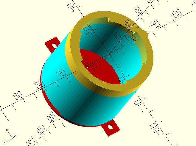
The original lens mount required some tuning to fit on my lens. It also took me a few test prints to get the orientation right. The final print time for the mount + tube was around 4h on my Ender 3 Pro, and another 1h for the camera mounting baseplate. The printing quality was at 0.2mm. Additionally, I printed a few spacers to adjust the flange distance without reprinting the entire thing. Luckily I could use the Anycubic i3 Mega in my hackerspace to parallelize the prints. The whole design does not require support structures.
Preparing the Raspberry Pi
The camera module I had came with a standard flat connector, which does not fit the CSI port of the Raspberry Pi Zero W. I had to order the correct cable, which cost me a few days. After receiving the cable, I installed the Raspberry Pi with Raspian since I just needed a stable platform to start experimenting. A note to beginners: You need to enable the CSI connector with raspi-config before using it.
Removing the camera lens
Removing the lens was more of an issue than I thought. For the first module, I tried to unscrew the lens with a pair of pliers, but that only wore the plastic without turning the lens. I resided to carefully removing the entire top half of the module and killed the IR filter during that. I also seem to have damaged the sensor, and the resulting images were not great.
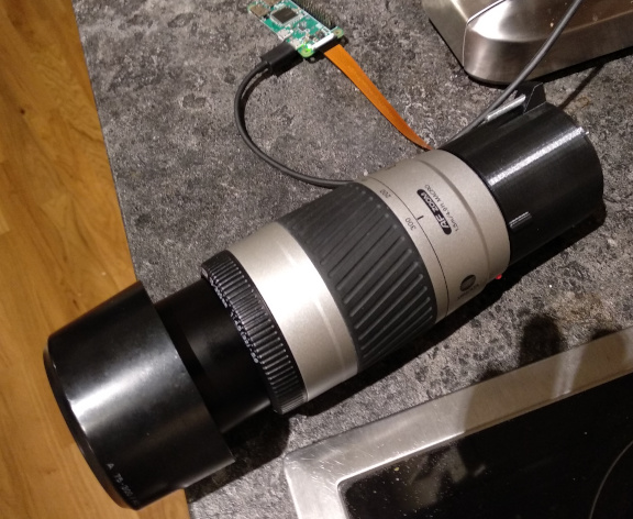
For the next module, I used the 3D-printed tool that is provided as a download here. Before trying to twist the lens, I carefully removed all visible glue with a small knife. After that, the tool gripped and I could carefully unscrew the lens. After the lens was removed, I mounted the camera module in my 3D-printed case and try it for the first time.

First experiments
My first experiments did not come out great. The images still had a red tint (like the images from the broken camera) and lacked detail. I opened the aperture of the lens to its fullest and played around with the focus ring. Et voila!
The image was still tinted red. When I removed the lens while filming, I understood why. The camera has a red LED lighting up when it is active! So the first sensor might not even have been wasted. To test the resulting images quickly and easily, I streamed the camera picture via UDP to my laptop:
ffmpeg -f v4l2 -input_format mjpeg -i /dev/video0 -vcodec copy -tune zerolatency -f mjpeg udp://[LAPTOP_IP]:1234
To open the stream I used vlc, reading the source IP and port of the UDP stream.
vlc udp://[RASPI_IP]:[SOURCE_PORT]
Testing in real life
To test the camera performance out in real life, I packed my GPD MicroPC and power bank and went to a nearby river to grab some shots. The weather was perfect, since it was relatively sunny, which should help compensate for the prototype’s tiny aperture. I settled at a bench and focussed on a boat on the other side of the river. For comparison, I took photos with my smartphone to give you a better impression of the scene. The measured distance of the shot was around 160m. Shooting over the water reduced the amount of turbulent air that usually emits from heated surfaces.

To keep the loading times low, I scaled the image down. To see the full resolution image (9MB) click here.
Grabbing the photos was a real challenge since it is nearly impossible to keep the camera steady by hand. I also lacked a way to mount it to a tripod. Every time I changed the focus, I moved it by a few millimeters. The best shot I grabbed was in focus and steady but rotated by about 30°. In a 100% magnification, the picture displays chromatic aberration (see red and green arrows).
The wide-open aperture likely causes these errors. When taking the next shot, I will try to reduce the aperture to improve the image quality. I could have reached the optical limit of the lens, but that’s hard to tell without taking some additional pictures. The reasonable zoom factor is, of course, limited by the lens diameter. I might be on the edge of this factor as well. The resulting angle of view is somewhere between a very zoomed hunting riflescope and a hobby astronomy telescope.
Outlook
I am delighted with the results, but of course, there is a lot to improve.
- Print a tripod-mount to make targeting and focussing easier
- Try shooting with a smaller aperture to reduce the aberrations
- Build a proper case, maybe even with a display, to make shooting easier
- Buy a cheap used teleconverter and try to improve the magnification even more
Until now, this project was a cheap and fun ride. I also leaned OpenSCAD during the way.